Tel.: +86 13358378970
E-mail: sales6@saulplc.com

Tel.: +86 13358378970
E-mail: sales6@saulplc.com
Jun. 25, 2023
1. Introduction to Simulator
Sampling time ∆ t=1s. The system is initially in a stable state, and the input flow that can be set is equal to the output flow (see table "Calculation", cell J21).
When t=0, it causes step interference to the discharge pipeline through the pump (see "Calculation" unit J24).
The actual level (present value) is calculated from the Mass balance (see page Calculations, cell C44: C2116). Obviously, in practical situations, there is a level transmitter that "reads" and communicates with the PV on the controller.
A Dead time can be put in the system (see "Calculation", cell J25) just to check the impact on the PID controller.
The algorithm PID determines the control action of the regulating valve, thereby changing the inlet flow rate.
The control valve has linear characteristics: Fin=% opening valve/100 * Fmax, in.
To disable differential actions, simply set Td=0 (refer to "Calculate" in cell J8), while to disable integral actions, set the value to 0 in cell J9.
2. Simulator adjustment
In the following data boxes, pink data can be modified, while blue data is calculated and cannot be modified.
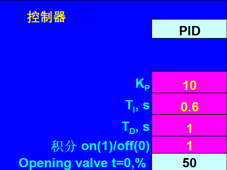
The following are the settings for the controller parameters

Among them:
KP represents the proportional effect
TI, representing the integral action time
TD, represents the derivative action time
Integration on (1)/off (0), where 1 is for opening the integration effect and 0 is for closing the integration effect
Opening valve, which is the input flow divided by the output flow multiplied by 100 (refer to cells J21/J17 * 100)
Controller action, positive or negative feedback
Direct, if PV>SP, CO (controller output signal) increases
Indirect, when PV>SP, CO (controller output signal) decreases
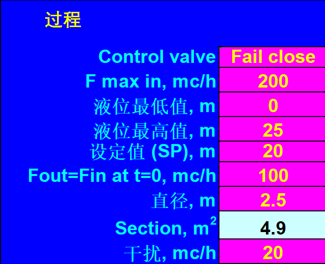
The following are the settings for process parameters

Among them:
Control valve, which is the type of valve
Fail close, represents the normally closed valve Fail open, represents the normally open valve
Fmax in, is the input flow rate
The lowest liquid level value represents the lowest liquid level value
The highest value of the liquid level, representing the highest value of the liquid level
Set value (SP), which is the set value
Fout=Fin, is the output flow rate
Diameter, is the diameter of the container, in meters
Section, is the dead zone section
Interference, steady-state error
Dead time is Dead time
3. PID debugging
For ease of debugging, the output graphics and parameter settings are now placed on the same page for easy viewing and parameter modification.
You can first fill in the type of controller based on the actual situation, whether it is positive or negative feedback, whether the type of control valve is a normally open or closed valve, the size of inlet and outlet flow, the high and low liquid levels of the storage tank, and other conditions. By adjusting the PID parameters, observe the changes in the graph.
Navigation
Add.: 9D, 9th Floor, Huguang Building, Hubin West Road, Siming District, Xiamen City, Fujian Province, China
Tel.: +86 13358378970
Mob.: +86 13358378970
E-mail: sales6@saulplc.com
WhatsApp: +86 13358378970
Wechat: +86 13358378970